Performance Validation Test
This page presents the Joint Tracker performance-validation script through a case study performed on a Trossen robot arm. The same workflow can be adapted to other robots, but the figures and videos below show one concrete Trossen validation run.
Use the performance-validation test after calibration and identification to verify that Joint Tracker improves real robot tracking on a trajectory you can inspect before execution. The test uses the identified model bundle in src/robot/models/current/joint_tracker, generates or loads a task-space trajectory, computes the Joint Tracker optimized command, streams both the original and optimized commands to the robot, records encoder readings, and reports tracking error.
At the end of each validation run, the script writes a self-contained HTML report named joint_tracker_performance_report.html. With the default output location, the report is generated under src/robot/performance_validation/joint_tracker/<RUN_TIMESTAMP>/ beside the task-space CSV (if user did not provide trajectory test) and validation JSON for that run.
Single-Speed Mode
single-speed is the default mode. Use it first to validate one trajectory before running a speed sweep:
bashpython3 -m robot.run joint_tracker_performance_validation \
  <ROBOT_IP> \
  --mode single-speed \
  --urdf-path <URDF_PATH>
If you do not provide a trajectory, the script generates a default task-space trajectory. Use --trajectory-center-xyz-mm X Y Z and --tcp-rpy-deg ROLL PITCH YAW together to set the test trajectory center in millimeters and its fixed TCP orientation in degrees. If these options are omitted, the center of the robot workspace is used. Use --help for more information.
To run your own task-space trajectory, pass a CSV with the expected columns:
bashpython3 -m robot.run joint_tracker_performance_validation \
  <ROBOT_IP> \
  --mode single-speed \
  --urdf-path <URDF_PATH> \
  --csv-trajectory-path <TASK_SPACE_TRAJECTORY_CSV>
The CSV should contain time_s, x_m, y_m, z_m, pitch_rad, yaw_rad, and roll_rad. The script uses inverse kinematics to convert the task-space path into joint space before Joint Tracker is used.
To make the selected trajectory faster, use --trajectory-speed-scale. A value greater than 1.0 shortens the trajectory duration before optimization and robot execution:
bashpython3 -m robot.run joint_tracker_performance_validation \
  <ROBOT_IP> \
  --mode single-speed \
  --urdf-path <URDF_PATH> \
  --csv-trajectory-path <TASK_SPACE_TRAJECTORY_CSV> \
  --trajectory-speed-scale 1.6
When a robot IP is provided in single-speed mode, the script opens a Viser animation automatically before it moves the robot. Inspect the robot, table plane, and reference trajectory for collisions or unsafe motion.
Viser animation for trajectory inspection
When the motion looks safe, press Ctrl+C in the terminal to stop the animation and continue to hardware execution. The robot then moves to the trajectory start, streams the original reference trajectory (Joint Tracker off), streams the optimized trajectory (Joint Tracker on), and records encoder readings for both runs.
Robot experiment execution video
The experiment video shows the real robot executing the validation trajectory after the Viser inspection step.
Expected Single-Speed Mode Outputs
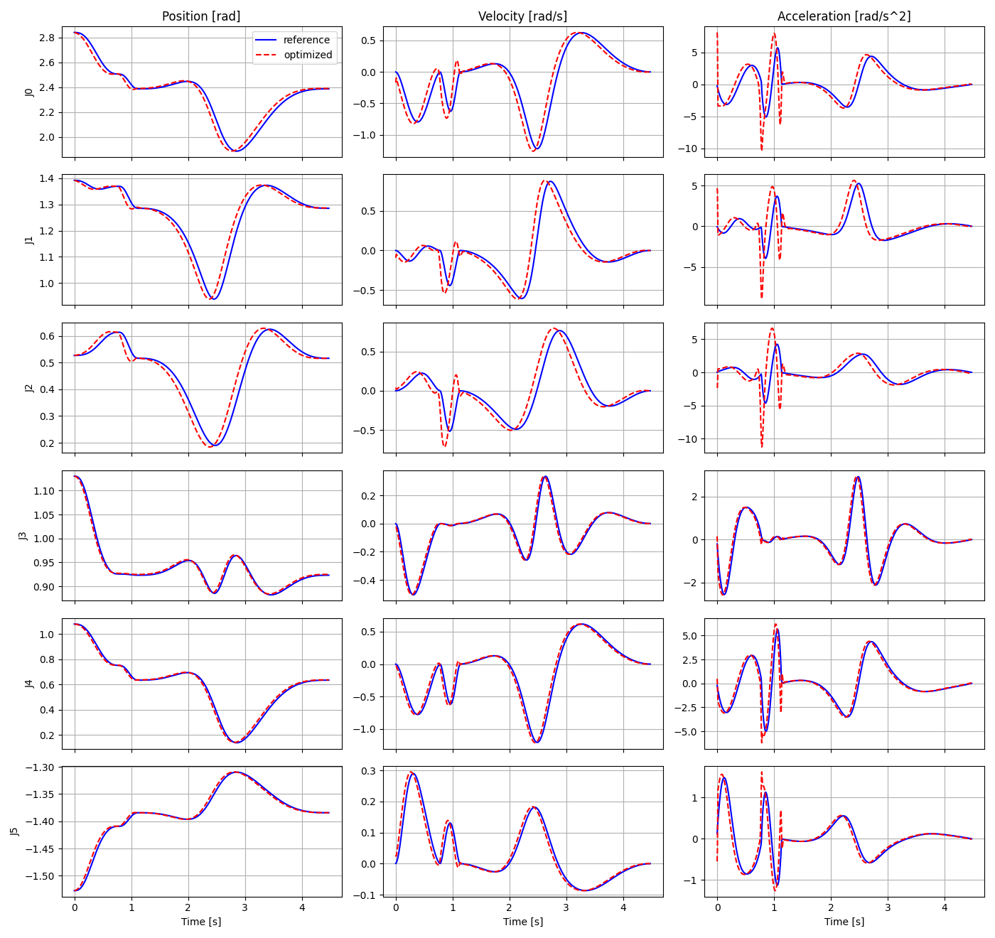
The figure below compares the reference command and the Joint Tracker optimized command for every joint. The columns show position, velocity, and acceleration. The optimized command is expected to differ from the reference because Joint Tracker reshapes the command to compensate the identified joint dynamics.
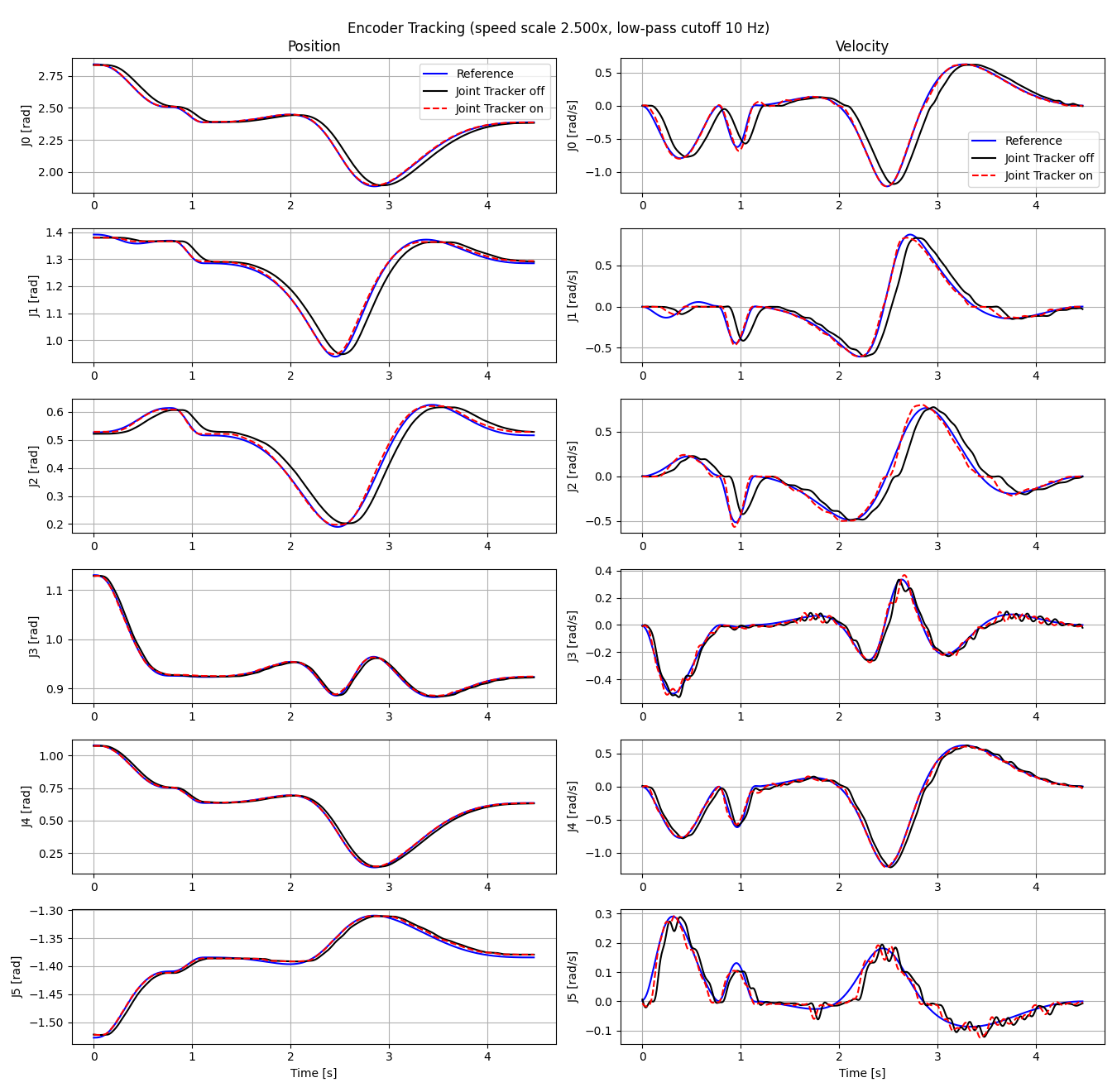
The encoder tracking figure compares the reference, Joint Tracker off encoder readings, and Joint Tracker on encoder readings for all joints. The left column shows position in radians, and the right column shows velocity in radians per second. Joint Tracker on should track the reference more closely.
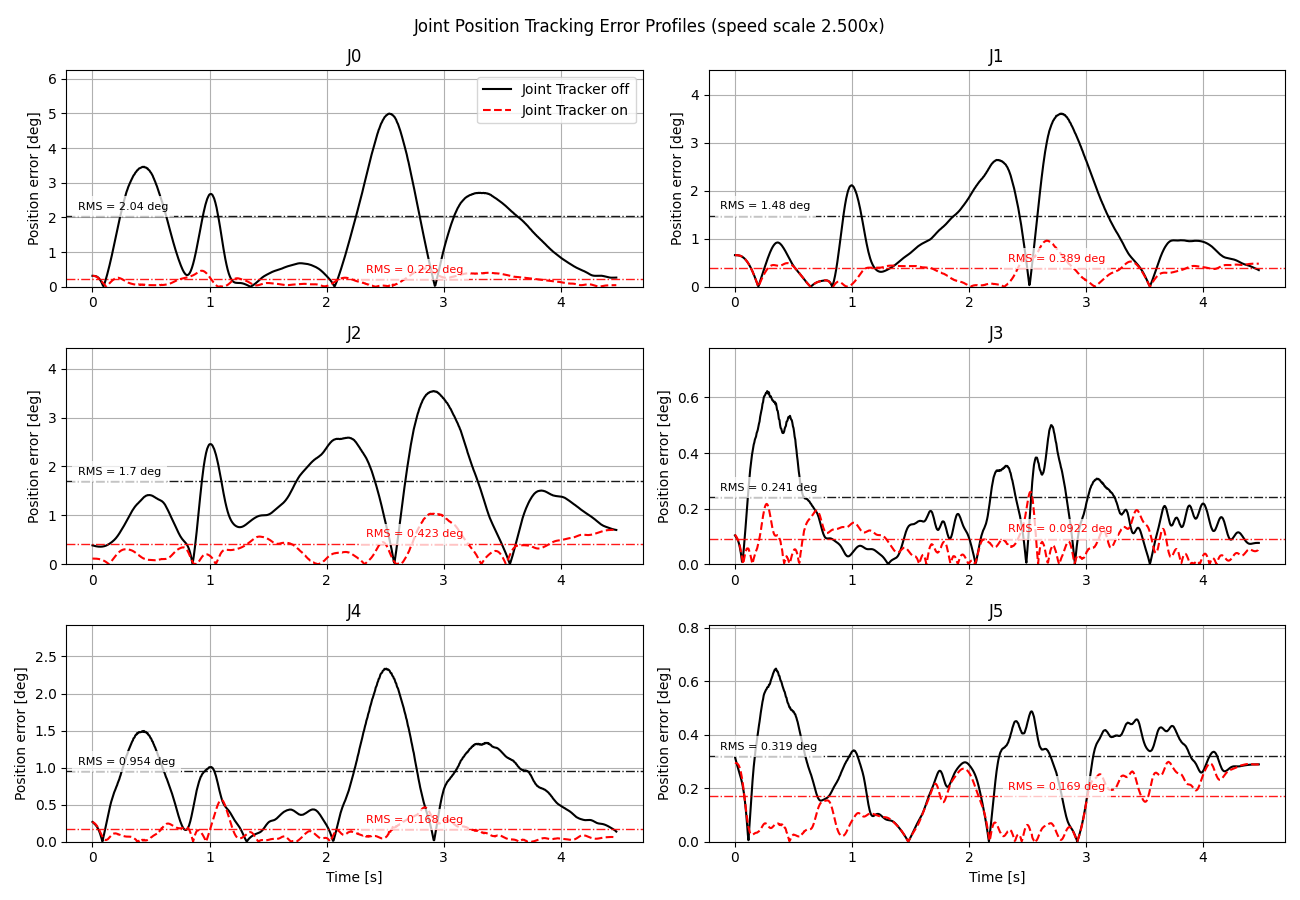
This joint-space error-profile figure plots position tracking error versus time for all six joints. Black solid curves show Joint Tracker off, red dashed curves show Joint Tracker on, and the dash-dot horizontal lines mark the RMS error for each profile.
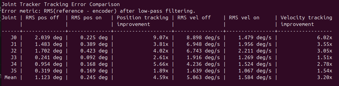
The single-speed terminal output also reports the joint space tracking error metrics directly, making it easy to validate the tracking error improvements in all joints when the Joint Tracker is used. The improvement columns are factors, so 4.00x means the Joint Tracker on error is four times lower than the Joint Tracker off error.
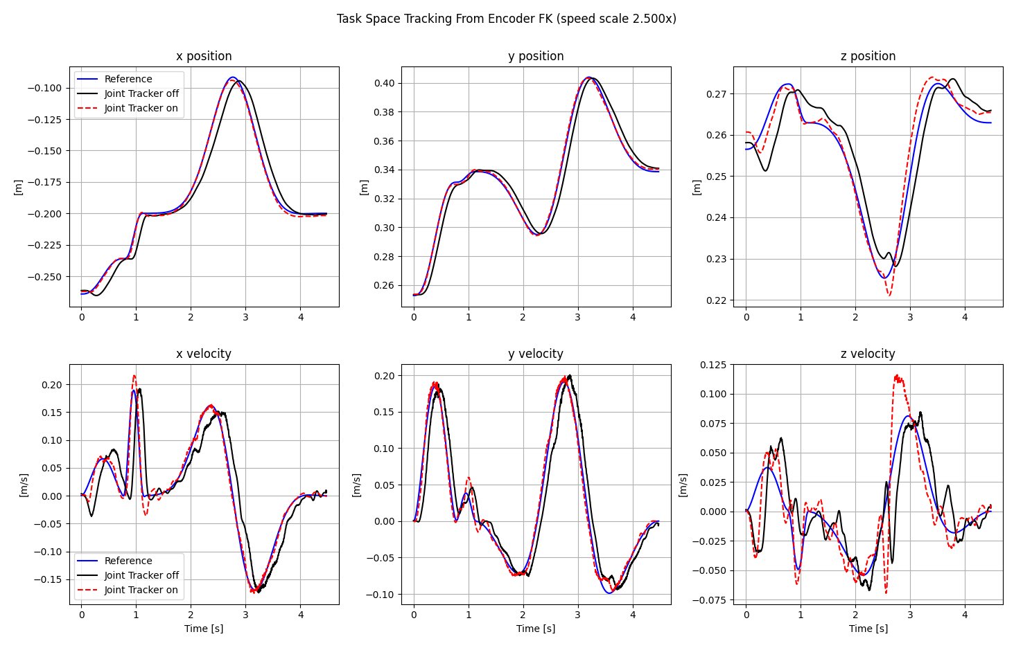
This task-space figure converts the filtered encoder readings through forward kinematics. The top row compares x, y, and z position, and the bottom row compares x, y, and z velocity. It shows whether the joint-level tracking improvement also improves the TCP trajectory tracking.
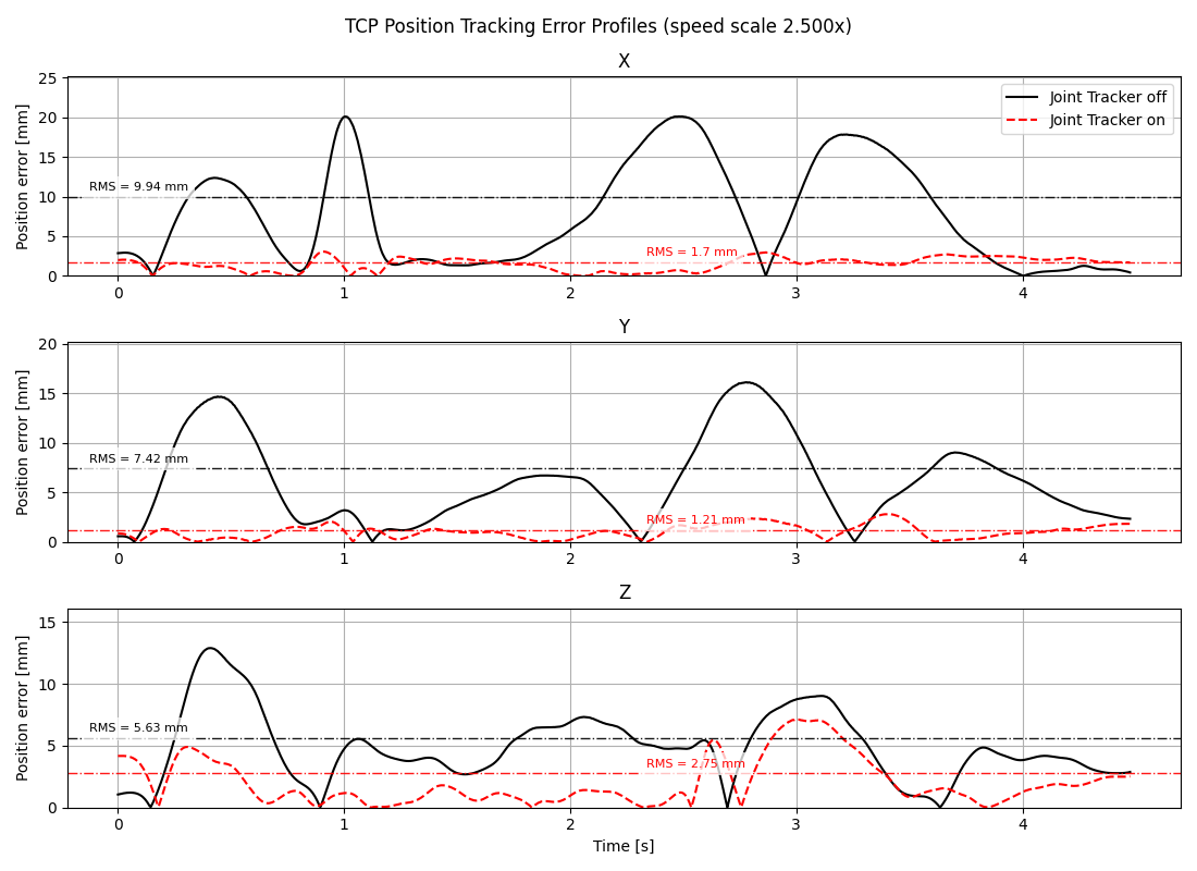
This TCP error-profile figure plots x, y, and z position tracking error versus time after converting encoder readings through forward kinematics. The RMS guide lines show the time-domain RMS tracking error for each axis.
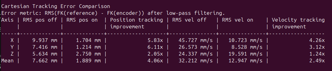
The terminal tables report RMS tracking error for Joint Tracker off and Joint Tracker on. The task-space table reports forward kinematics (FK) based x, y, and z position and velocity error.
Multiple-Speed Mode
After a single trajectory looks safe, use multiple-speed mode to quantify how much Joint Tracker helps as trajectory speed increases:
bashpython3 -m robot.run joint_tracker_performance_validation \
  <ROBOT_IP> \
  --mode multiple-speed \
  --urdf-path <URDF_PATH>
This mode uses the same base trajectory selection as single-speed mode. If --csv-trajectory-path is provided, every speed scale uses that user-provided trajectory. If no CSV is provided, the script generates the default validation trajectory once and retimes that same path for every speed.
The sweep starts at 1.0x and increases with nominal 0.3x spacing. The default top speed scale is 2.5x. To set a different top speed scale, use --speed-sweep-top-scale:
bashpython3 -m robot.run joint_tracker_performance_validation \
  <ROBOT_IP> \
  --mode multiple-speed \
  --urdf-path <URDF_PATH> \
  --csv-trajectory-path <TASK_SPACE_TRAJECTORY_CSV> \
  --speed-sweep-top-scale 2.8
Multiple-speed mode does not use Viser. It preflights and optimizes all speed scales first, then streams Joint Tracker off and Joint Tracker on at each speed. At the end, it prints a compact speed-sweep summary and writes the HTML report to the validation run folder. The report includes RMS tracking error versus speed scale and the detailed encoder traces for the highest-speed case.
Expected Multiple-Speed Outputs
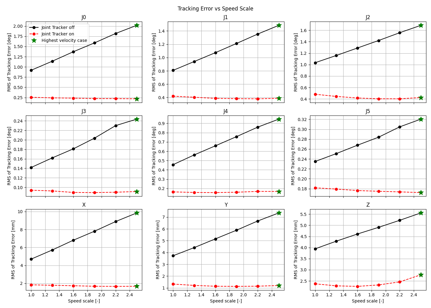
The 3 by 3 speed-sweep figure shows RMS tracking error on the y-axis and speed scale on the x-axis. The first six panels are joint-space position error for joints J0 through J5. The last three panels are task-space x, y, and z position error from encoder FK. Black solid curves are Joint Tracker off. Red dashed curves are Joint Tracker on. The green star marks the highest velocity case, which is the condition used for the final detailed encoder plots.
For the highest-speed sweep case, the report also includes the same detailed joint-space and task-space outputs shown in the single-speed section, which is the same as the outputs presented on the single-speed mode in this case study.