KineCal Tutorial
This tutorial explains how to prepare the kinematic calibration hardware, collect KineCal datasets, and run cloud identification to generate a calibrated robot URDF and performance report.
1. Calibration Hardware
Reforge supports two calibration kit options. First, you can order the calibration kit from Reforge Robotics and perform the calibration in a plug-and-play manner. Second, you can follow the Make Your Kit tutorial to assemble your own kit. In both cases, the final kit should look like the image below.
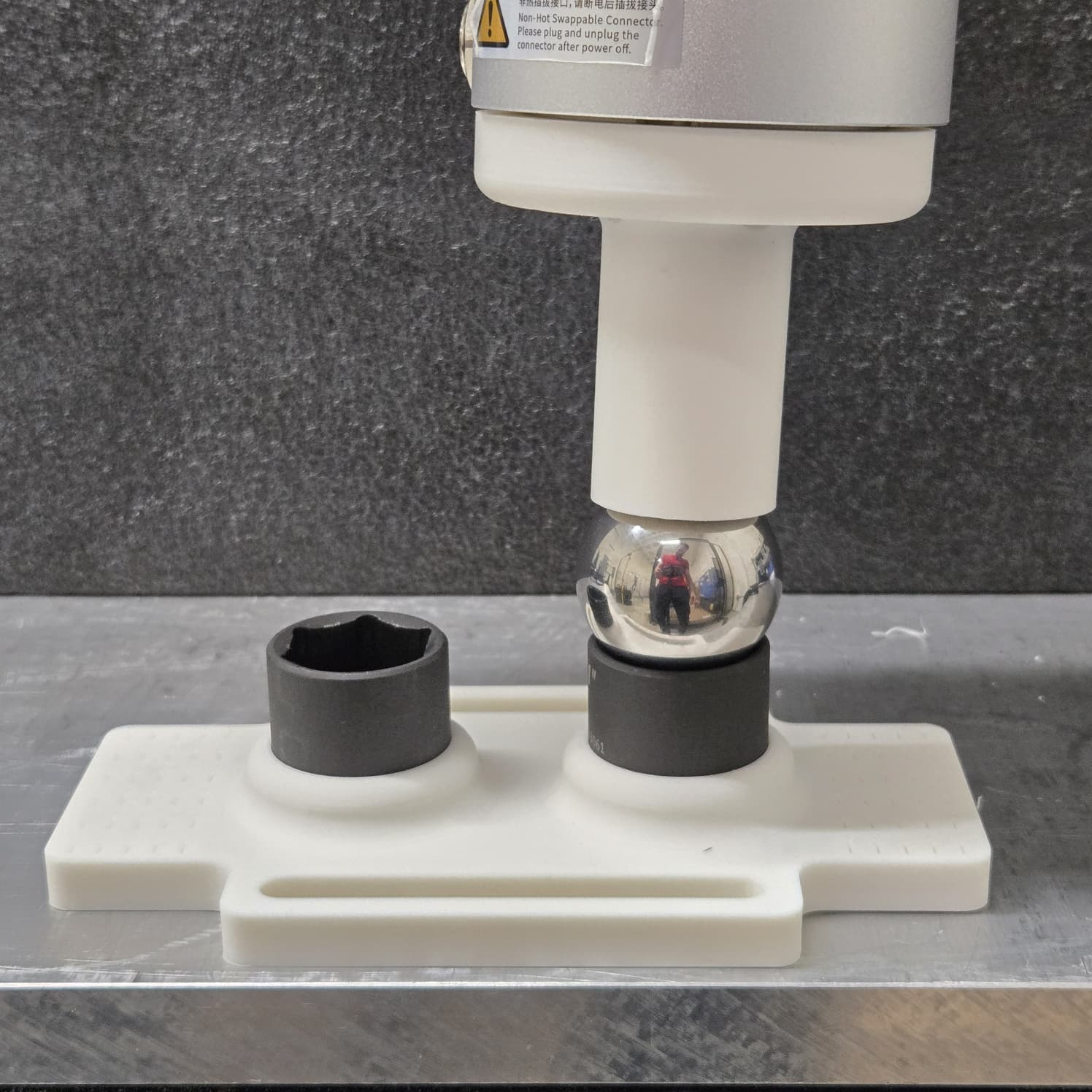
Note that if you purchased a Reforge kit, the socket offset will be provided on the calibration letter. If you built your own kit, the socket_offset_mm estimated by your measurements should be used in the model identification phase. The Make Your Kit tutorial explains how to measure socket_offset_mm.
2. Calibration and Identification of the Robot Model
2.1 Setup the SDK
Go over the First Steps from Get Started to generate your API token and robot ID and install the Reforge Robotics SDK.
Before continuing, confirm that you have:
- The calibration hardware kit.
- The Reforge API token.
- The Reforge robot ID.
- The Reforge Robotics SDK installed in your robot interface environment.
2.2 Check the URDF and Download Robot STL Files
The default Covalent KineCal data collection workflow is semi-automated, meaning the robot moves to optimized poses that improve kinematic-error identification with fewer data points. This workflow requires the robot STL mesh files for collision checking so the planner can reject paths that would collide with the table where the calibration plate is attached. Manual collection skips collision planning and does not require the mesh files.
Before running calibration, verify two things:
- The robot mesh files are present in the repository.
- The URDF
<mesh>paths point to those local files for both<visual>and<collision>geometry.
In this example, the robot (UF850) mesh files are stored next to the URDF under:
textsrc/robot/urdf/meshes/uf850/visual/
src/robot/urdf/meshes/uf850/collision/
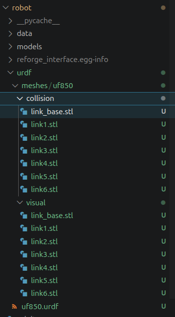
The URDF should point to the corresponding files. For example, link_base should have mesh filenames like:
xml<visual>
  <geometry>
    <mesh filename="meshes/uf850/visual/link_base.stl" />
  </geometry>
</visual>
<collision>
  <geometry>
    <mesh filename="meshes/uf850/collision/link_base.stl" />
  </geometry>
</collision>
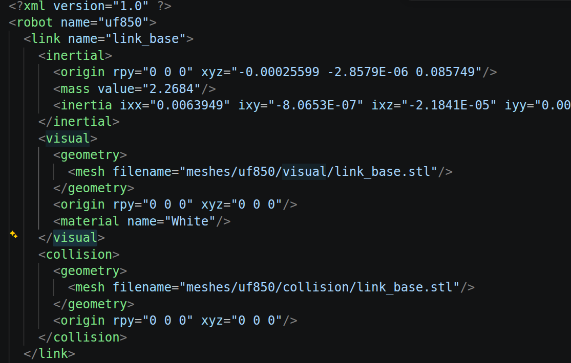
Repeat this check for every robot link.
2.3 Run the Calibration
Choose either the semi-automated or manual collection workflow for each workspace region you want to calibrate.
Semi-Automated Collection
The semi-automated workflow plans the ideal robot poses for each socket to maximize data quality. It then plans the motion to each pose slightly above the socket, then transitions the robot to teaching/hand-guided mode for the user to move the robot to make contact with the socket. Then, once the user lifts the robot out of the socket to the original height, the robot moves to the next pose and repeats the process until all poses are collected.
Run data collection from the repository root:
bashcd <path-to-reforge-interface>
source venv/bin/activate
python3 -m robot.run kinecal <YOUR_ROBOT_IP>
For example:
bashpython3 -m robot.run kinecal 192.168.1.231
Below you can find the calibration video. It shows the expected interaction you should have with your robot and computer during data collection. In the demo, calibration is simulated in one robot workspace region. The number of insertions is shortened in the video, but a full experiment should take about 10 to 15 minutes for each workspace region.
{Video will be added soon}
Manual Collection
Use full-manual collection when you need to move the robot yourself in teaching/hand-guided mode. In this workflow, the SDK does not change robot modes, plan trajectories, or command robot motion.
bashpython3 -m robot.run kinecal <YOUR_ROBOT_IP> --manual
Before continuing, put the robot in teaching/hand-guided mode. For each socket, fully seat the sphere and capture the current pose with Enter or the flange button. Manual collection always starts with socket 1 active. Press s to switch between sockets at any time and d to finish the collection invocation.
KineCal recommends at least 30 total samples per socket. If either socket has fewer samples, KineCal warns and asks you to press d again, but it does not prevent completion.
Resume or Append to a Collection
Every accepted sample is checkpointed. If collection is interrupted, continue using the existing dataset folder instead of starting over:
bash# Resume an interrupted semi-automated collection
python3 -m robot.run kinecal <YOUR_ROBOT_IP> \
  --data-folder <EXISTING_DATASET_FOLDER>

# Continue with manual collection or append more manual samples
python3 -m robot.run kinecal <YOUR_ROBOT_IP> \
  --manual \
  --data-folder <EXISTING_DATASET_FOLDER>
The supported continuation rules are:
- An incomplete semi-automated collection may resume in semi-automated mode; KineCal collects only the missing samples.
- An incomplete or completed semi-automated collection may continue in manual mode.
- A manual collection may continue in manual mode, with samples accumulating across invocations.
- Once manual collection starts, that dataset cannot return to semi-automated collection.
- A completed semi-automated collection cannot run a second semi-automated collection.
Note that you should only continue collection into the same dataset if the calibration plate has not been moved. If it has been moved, a new data collection should be started.
After Collection
Run your chosen collection workflow once for each workspace region you want to calibrate. At the end of each run, the terminal prints the folder where the calibration dataset was saved. Without --data-folder, KineCal creates a new timestamped folder. With --data-folder, it continues the selected folder. Pass each completed dataset folder into model identification. Identification rejects an in-progress dataset until collection finishes successfully.
Example output folder and terminal final print:
text/home/robot1234/controlbox/apps/reforge-interface/src/robot/data/kinecal/datacol/20260625_1742

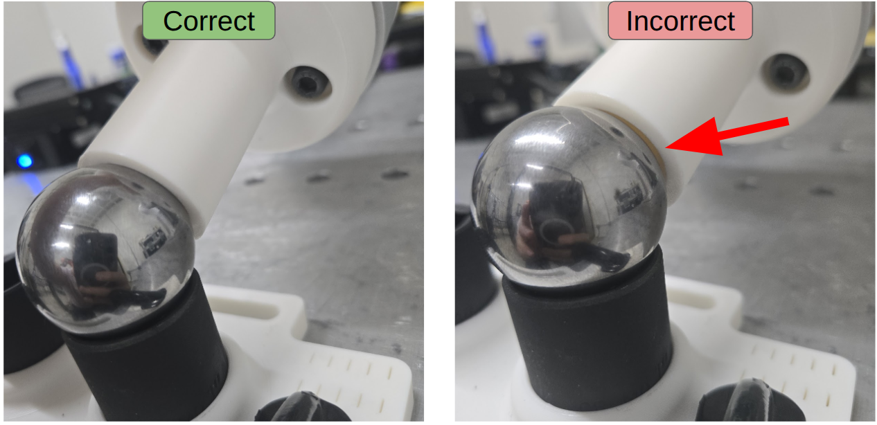
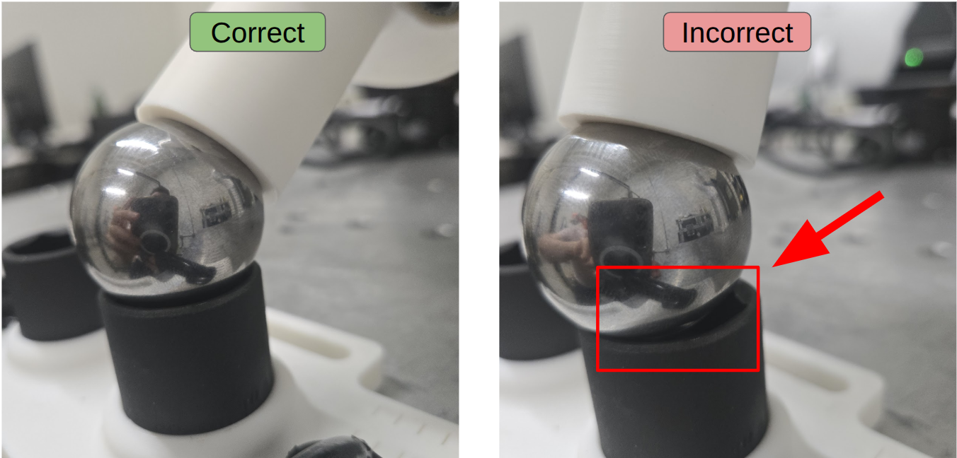
Before recording each pose, make sure the end-effector is fully engaged with the sphere and the sphere is centered in the socket. Incorrect contact can negatively affect calibration.
Flange Button
The calibration video shows data collection by pressing Enter for every robot pose. Some robots also have a robot flange button that can be used instead of the keyboard.
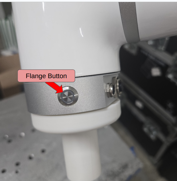
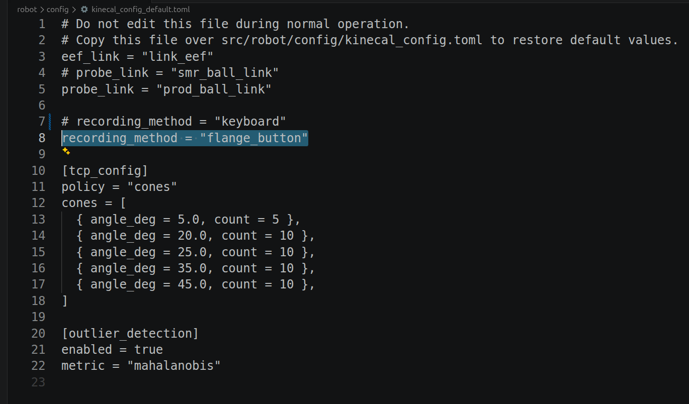
To change from keyboard recording to flange-button recording, open src/robot/config/kinecal_config.toml, uncomment recording_method = "flange_button", and comment recording_method = "keyboard". Save the file and run the experiment normally.
toml# recording_method = "keyboard"
recording_method = "flange_button"
2.4 Run the Model Identification
After collecting a workspace dataset, run cloud identification with your API token and robot ID from your account in the Reforge Robotics app.
bashcd <path-to-reforge-interface>

python3 -m robot.run identify \
  <REFORGE_API_TOKEN> \
  <ROBOT_ID> \
  <DATA_FOLDER>
| Argument | Description |
|---|---|
<REFORGE_API_TOKEN> | Reforge Cloud API token. |
<ROBOT_ID> | Reforge robot ID. |
<DATA_FOLDER> | Calibration dataset folder generated by KineCal data collection. |
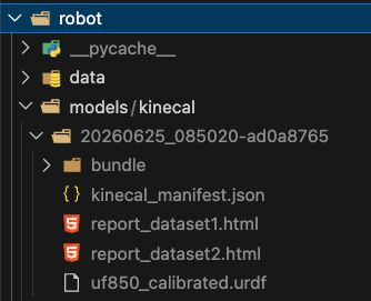
When identification finishes, the API returns a calibrated URDF trained with the submitted dataset and a performance report describing the accuracy and precision improvement. Results are extracted under:
textsrc/robot/models/kinecal/<timestamp-results-id>/
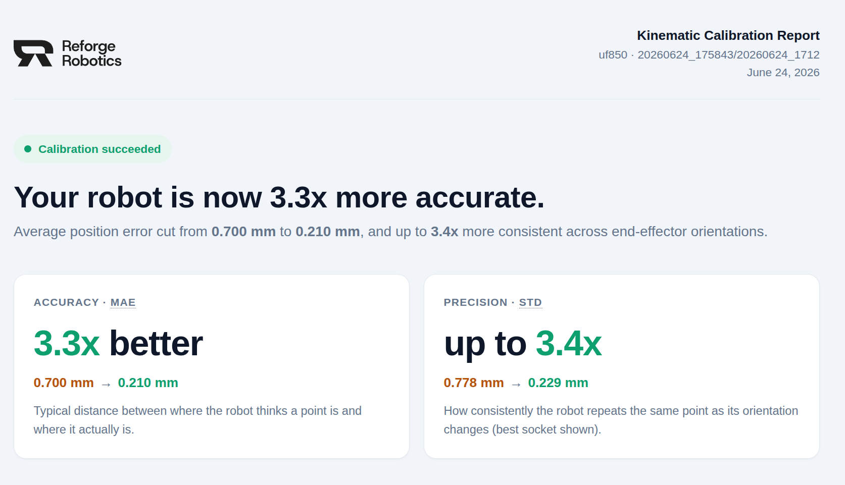
A successful identification generates a performance report like the example below.
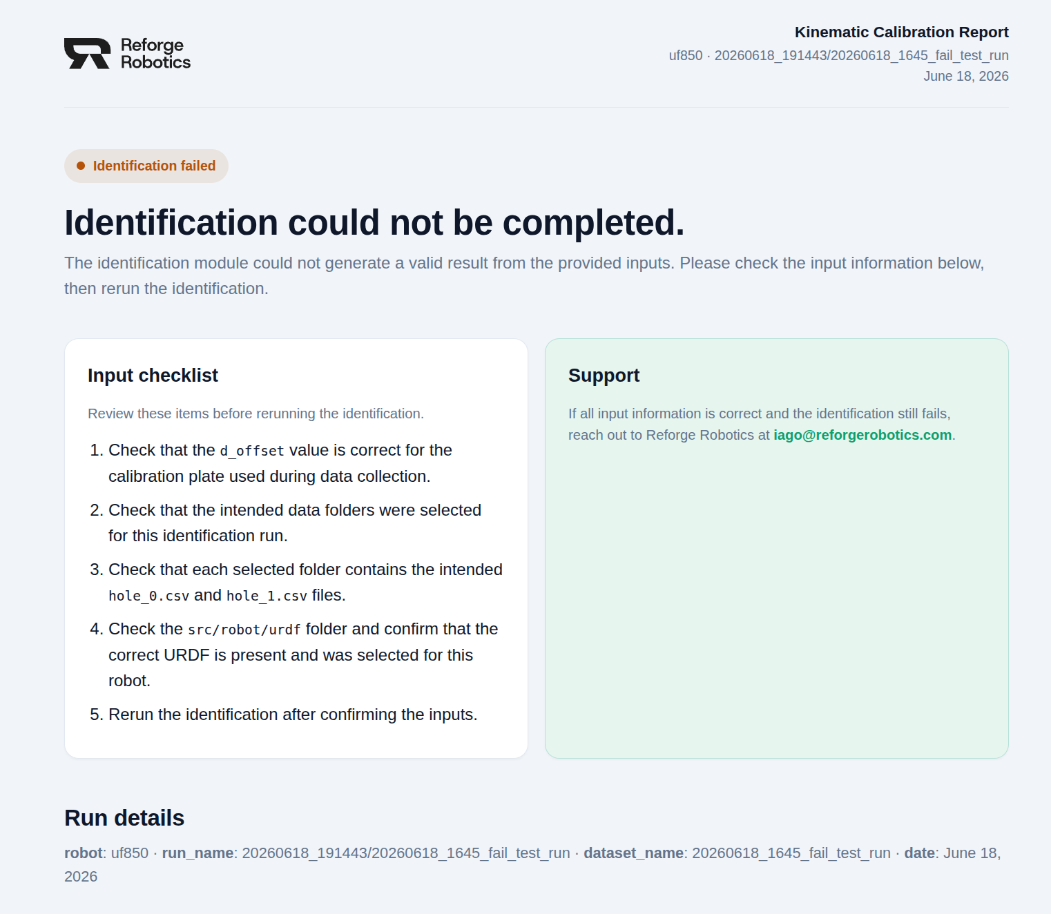
If identification fails, the report explains what happened and gives instructions on how to proceed. Common input issues are an incorrect data-folder path or calibration data that was recorded with poor socket contact.
3. Using the Robot Model
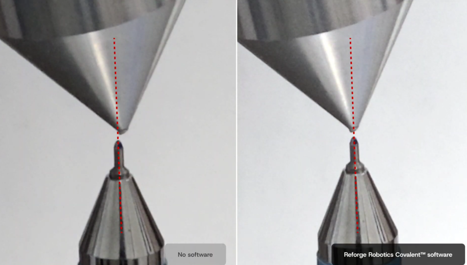
After identification finishes, you can use the calibrated kinematic model directly as a calibrated URDF or through the Reforge control module, which corrects robot kinematic error for a desired trajectory. The image below visually demonstrates the improvement calibration can bring to the robot. Refer to the KineCal Control page to learn how to use the Reforge kinematic controller.