

Making your calibration kit
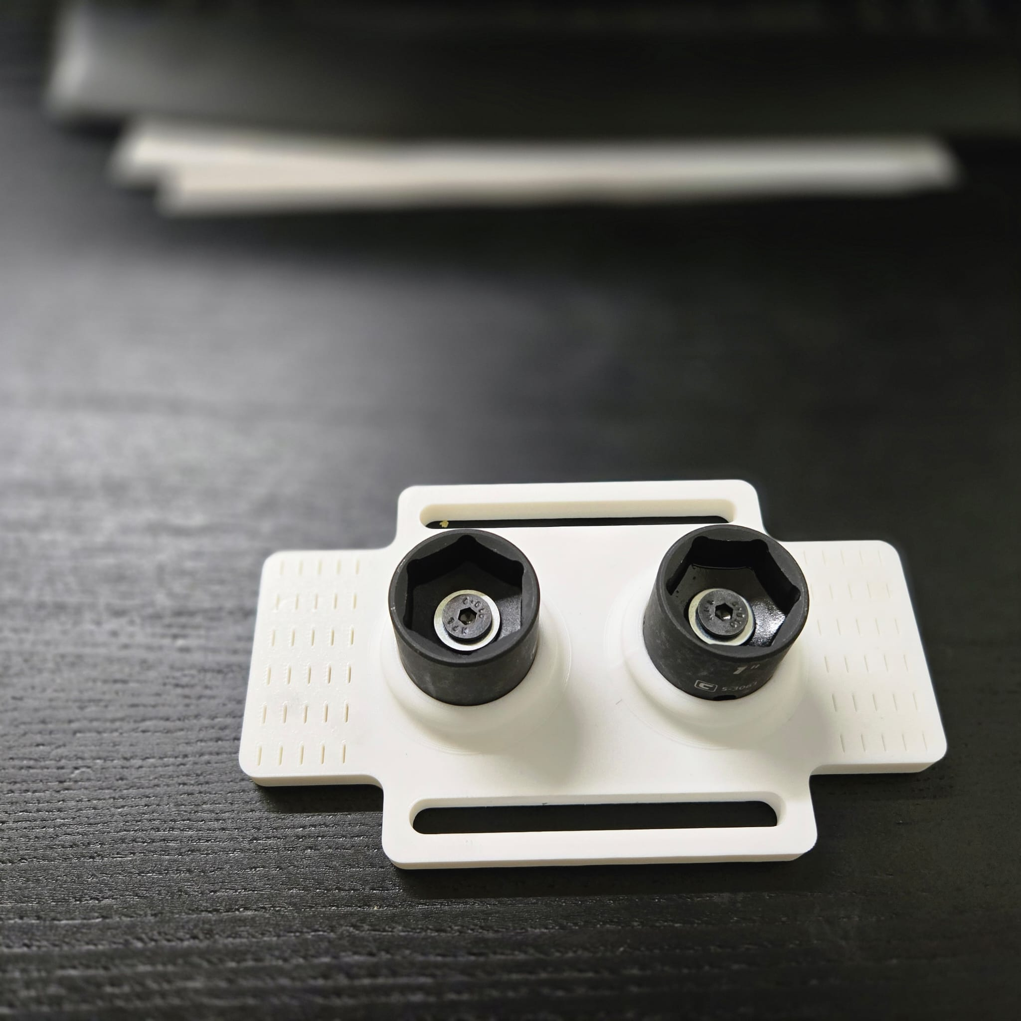
This tutorial guides you through building your own calibration kit. By the end of the tutorial, you should have assembled the kit and measured the offset between the calibration sockets. The completed calibration kit is shown below.
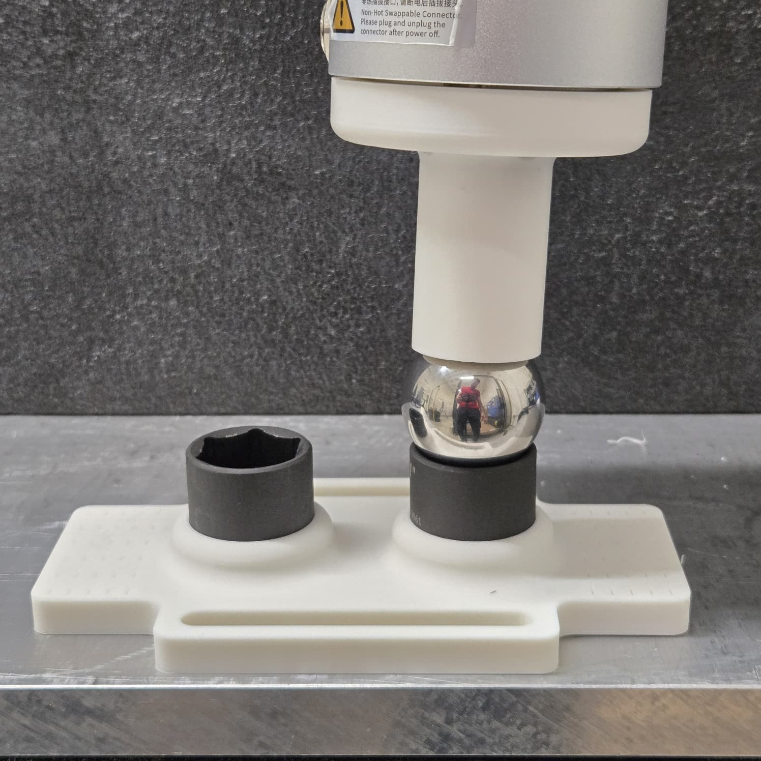
Bill of materials and 3D-printed parts
The bill of materials for the plate and end-effector is less than $35, and assembly takes less than 5 minutes once the parts are fully printed. Follow this tutorial in order to assemble and measure your kit.
| Item | Quantity | Link |
|---|---|---|
| Super glue | 1 unit | Gorilla Super Glue 15 gram, clear |
| 1 inch socket | 2 units | Amazon product page |
| 1.5 inch sphere | 1 unit | PGN chrome steel bearing ball |
| M6 flat head socket screw, length 30 mm | 2 units | Amazon product page |
| M8 flat washer | 2 units | Amazon product page |
| M6 nylon insert locknut | 2 units | Amazon product page |
| M6 screws, length 12 mm (these are for the part attached to the robot, not the calibration plate) | 4 units | Amazon product page |
Download the printed-part files:
Assemble the calibration kit
Wear safety goggles and gloves while assembling the kit, especially when using super glue.
Step 1: Remove support material
After printing the parts, remove the support material from the nut slots on the back of the 3D-printed plate.
Step 2: Secure the plate and apply glue
Fix the plate to a table using clamps or the screw slots. The plate was designed to support higher loads than typical 3D-printed parts, so secure it firmly before pressing the sockets into place.
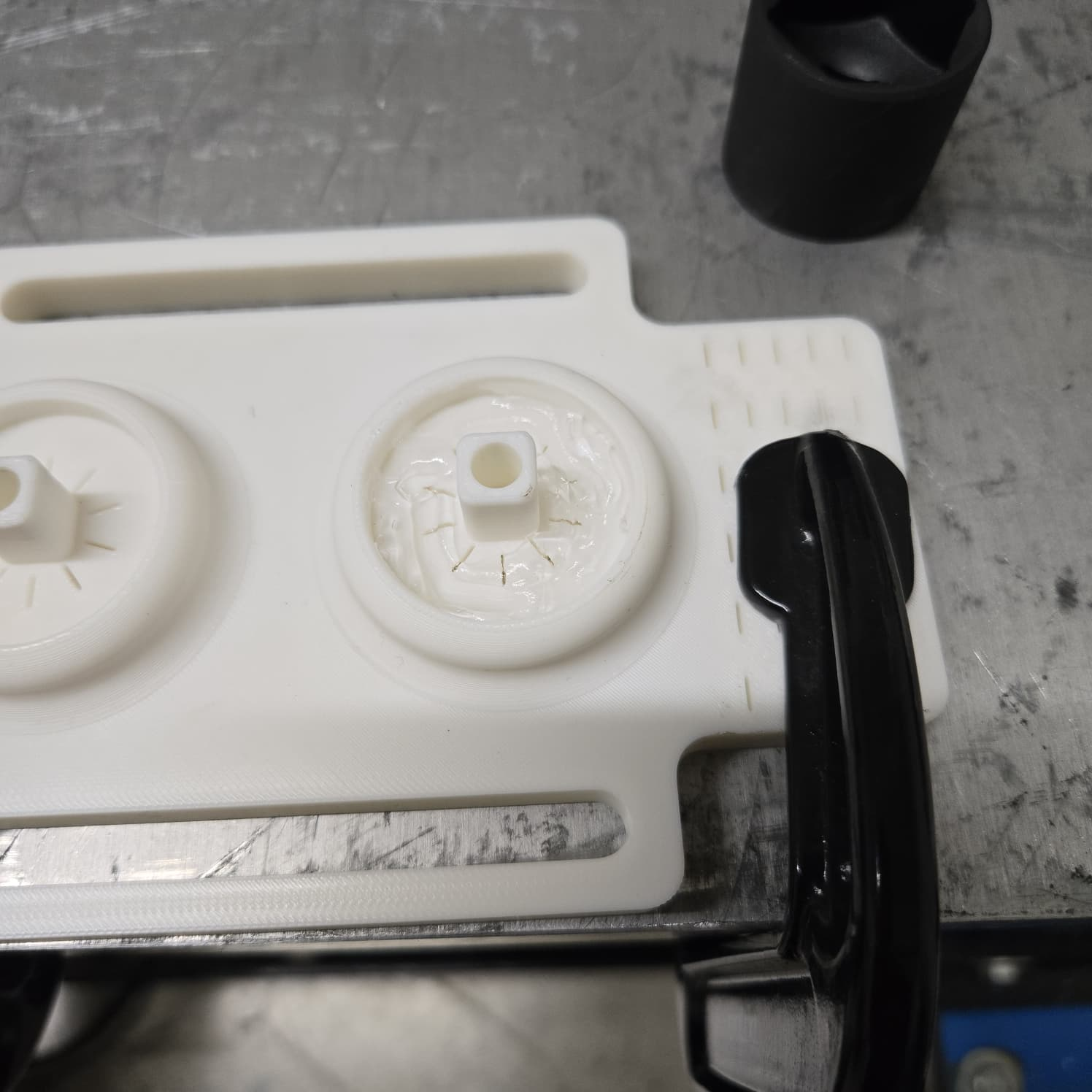
Spread super glue on the surfaces of the socket slots, as shown below.
Step 3: Insert the sockets
Insert the sockets into their slots. A tight fit is expected, so press each socket firmly against the 3D-printed plate or use a rubber mallet to help seat it. The plate was reinforced around the socket slots and should not break from rubber mallet impacts.
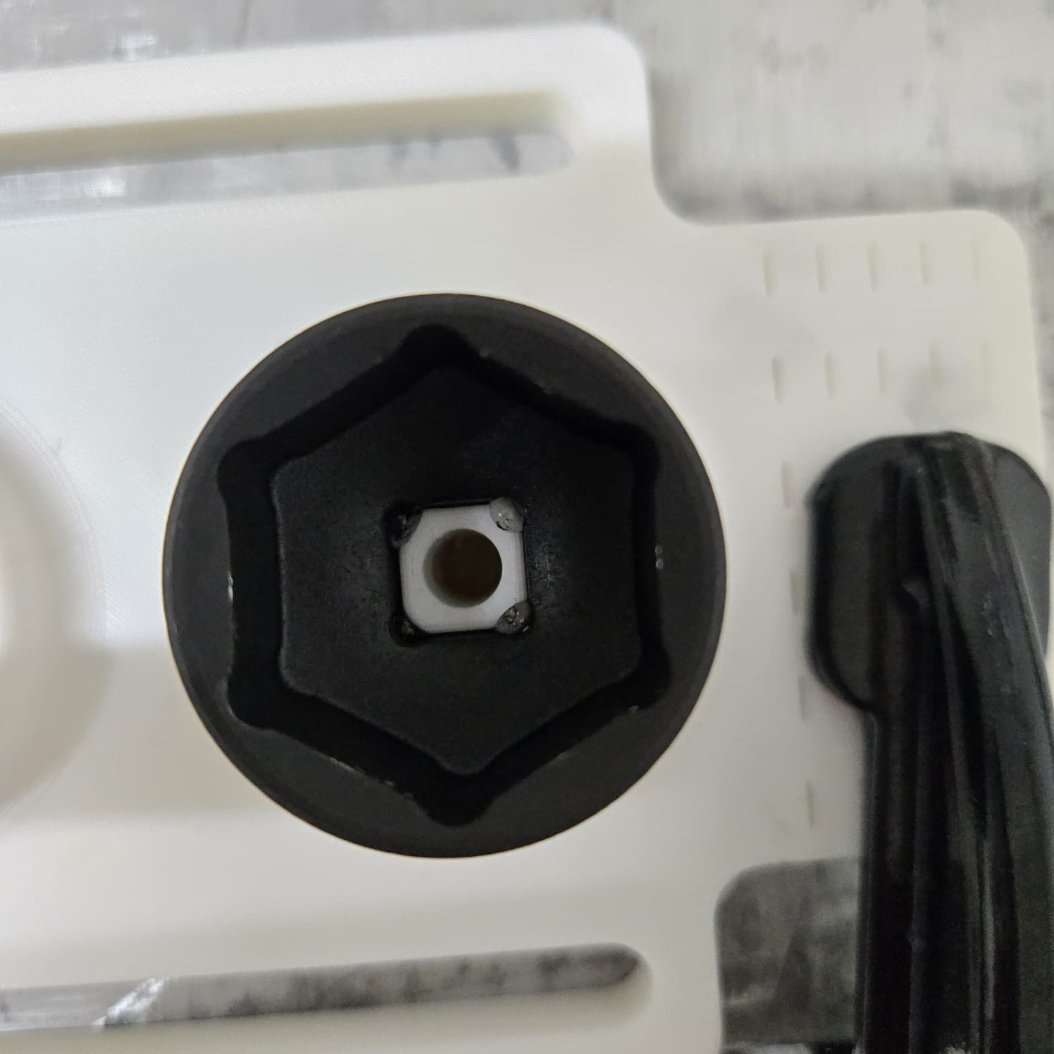
Make sure the back of each socket is fully inserted and flat against the slot surface. A tilted socket will reduce the quality of the calibration data. Do not strike the sockets directly with a steel hammer because it can damage the socket edges and reduce calibration quality.
The front of the assembled socket should look like this.
Step 4: Insert the screws and washers
Insert the M6 screws with the M8 washers into the socket slots.
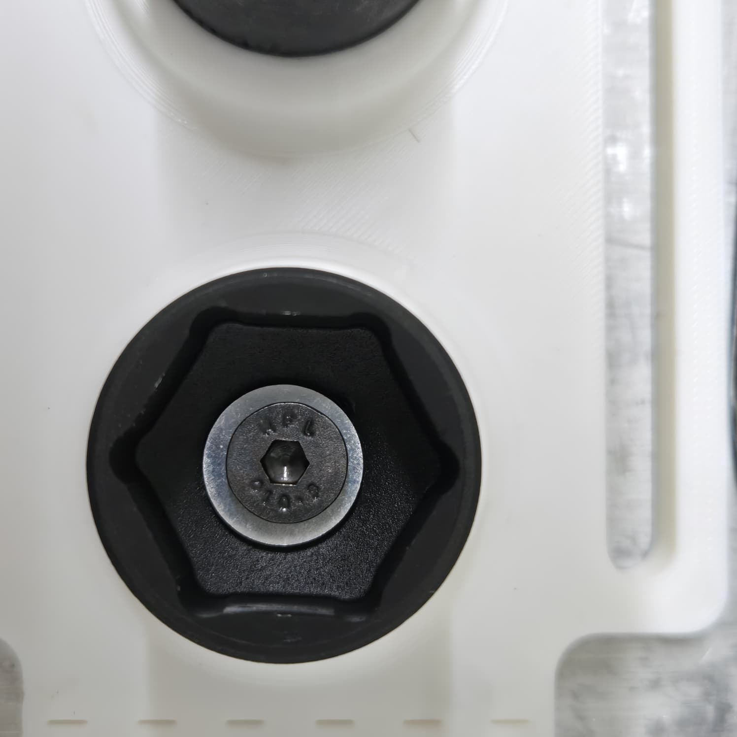
The back of the part should expose the screw ends before the locknuts are installed.
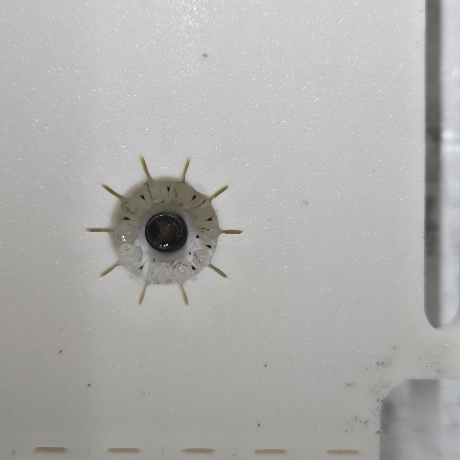
Step 5: Install the locknuts
Place each M6 locknut inside the drive wrench socket, then tighten the screws firmly. The goal is for the metal sockets to be rigidly attached to the 3D-printed plate so the plate would fail before the sockets could move.
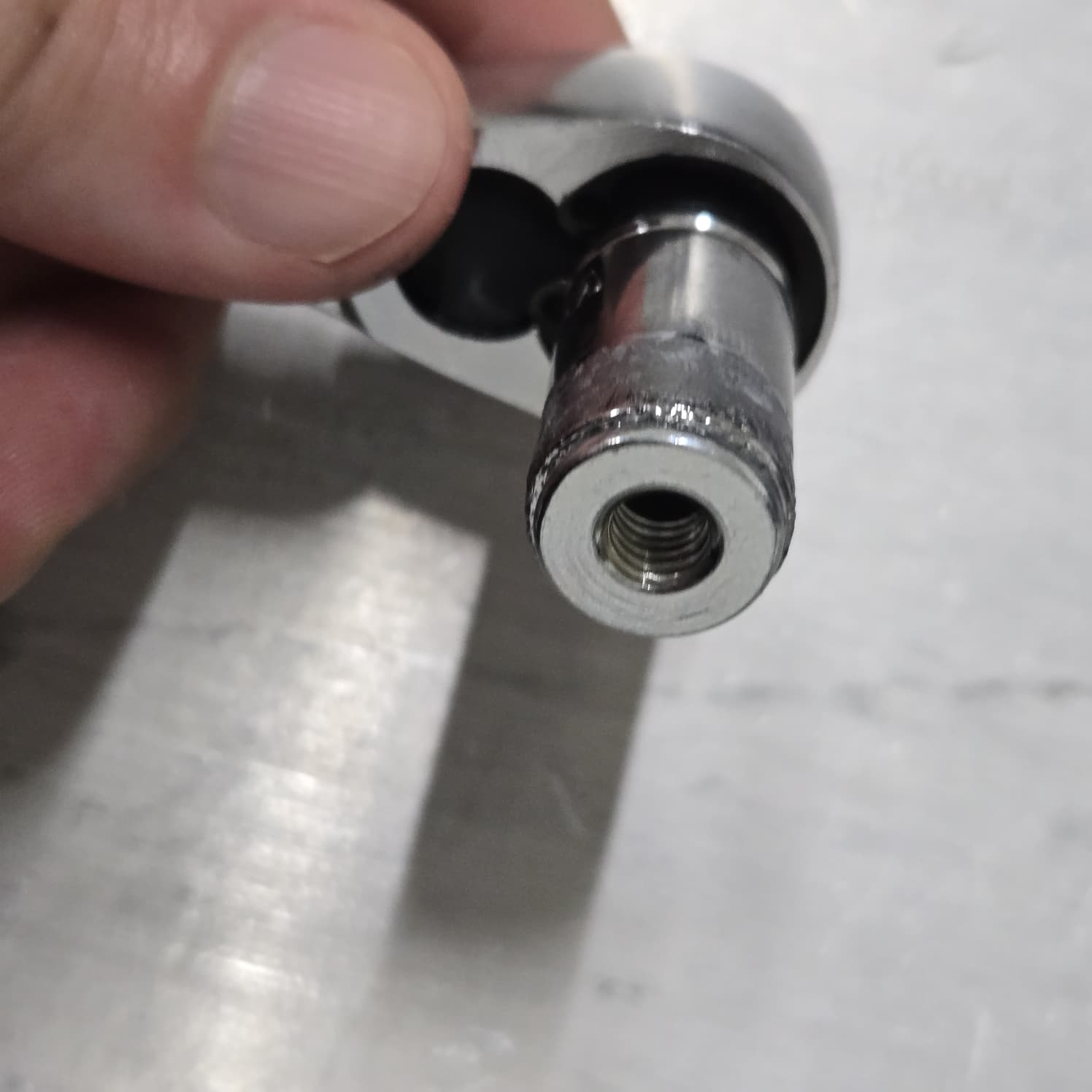
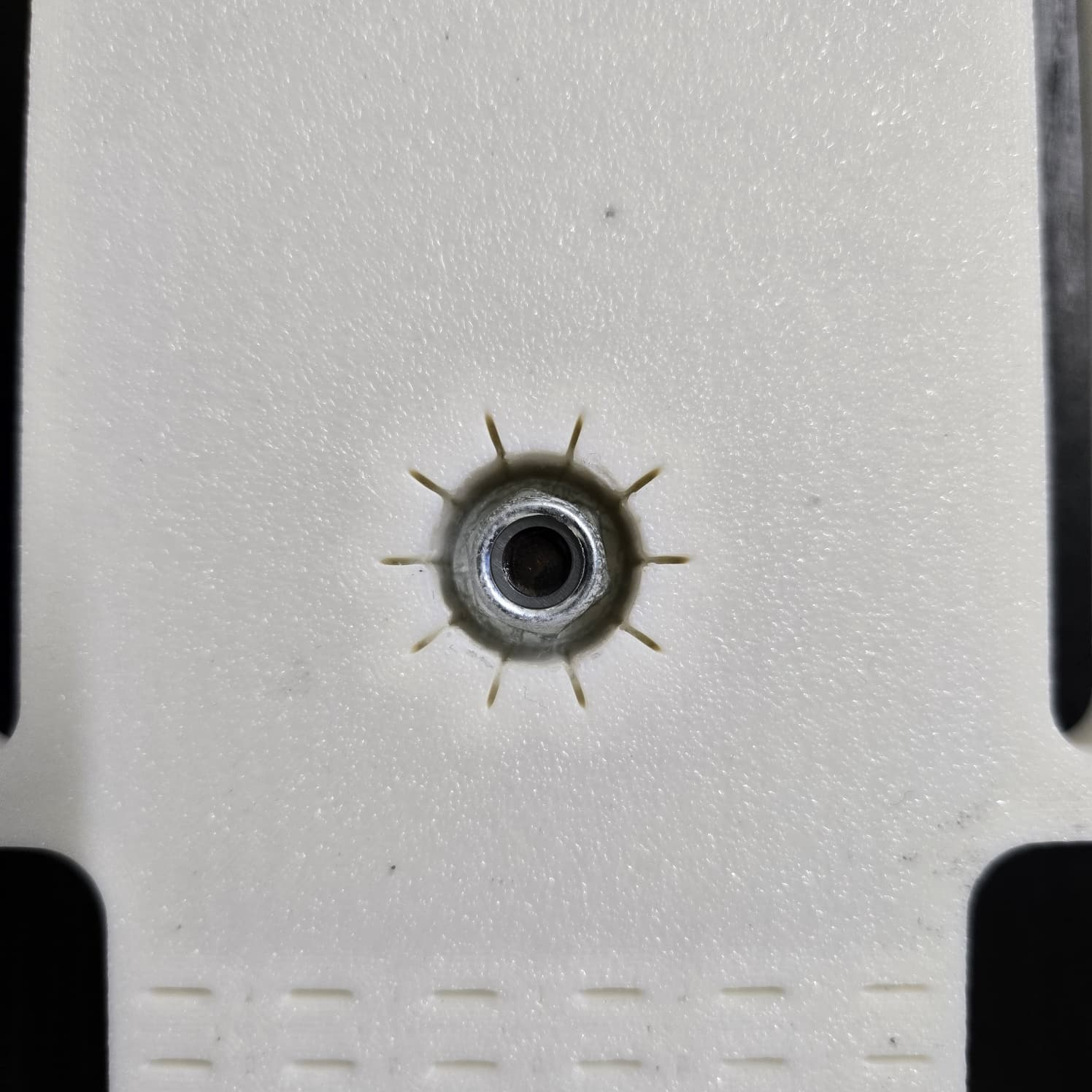
After tightening, each locknut should be seated against the back of the plate.
The final assembly should look like this.
Measure the socket offset
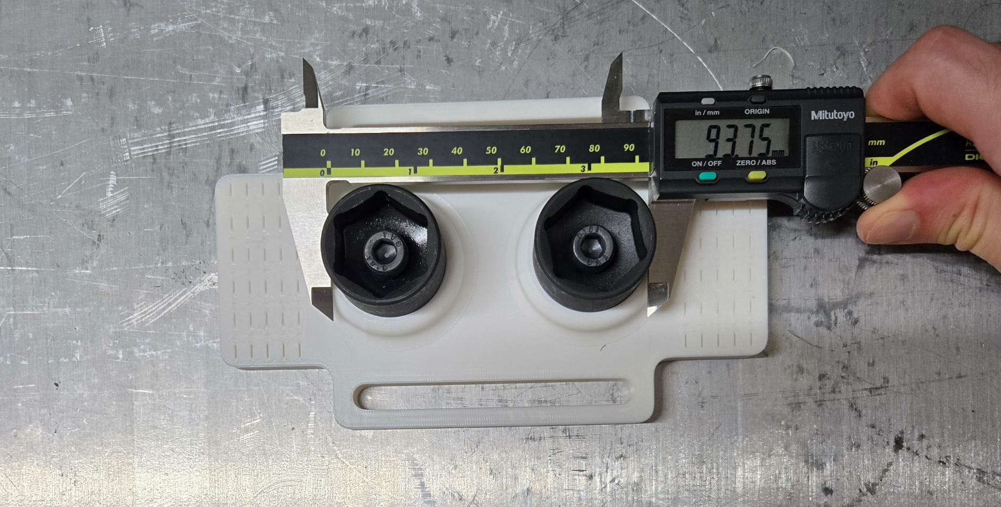
If you built the calibration kit yourself, measure the socket offset before running identification. Use calipers and repeat each measurement 10 times:
- Measure the total outside length across both sockets.
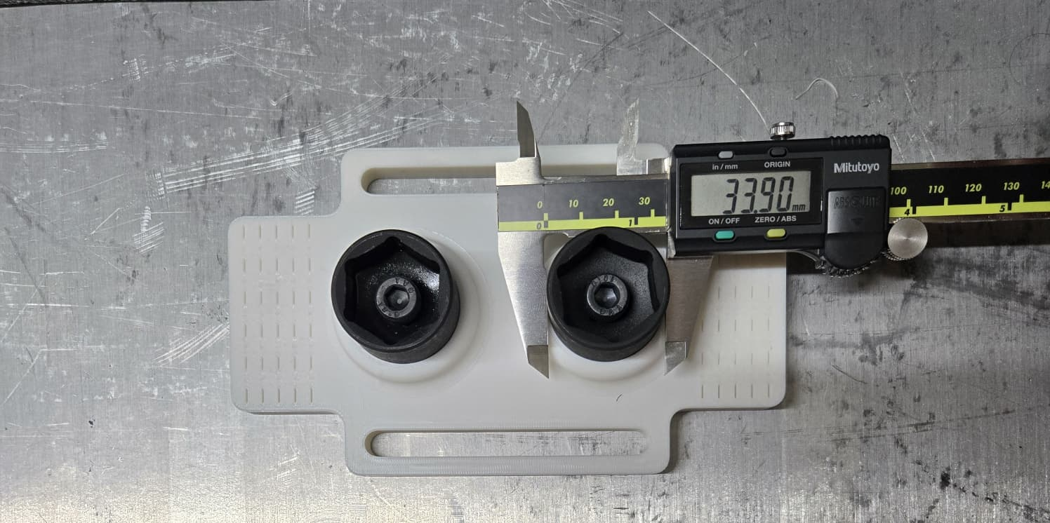
- Measure the outer diameter of socket 1.
- Measure the outer diameter of socket 2.
- Average each set of 10 measurements.
- Compute the socket center distance:
textsocket_offset_mm = mean_total_length_mm - (mean_od_socket_1_mm / 2 + mean_od_socket_2_mm / 2)
Measure the total length across the outer socket edges as shown below.
Measure each socket outer diameter as shown below.
If you purchased a Reforge kit, the socket offset will be provided on the calibration letter. If you built your own kit, use the socket_offset_mm estimated by your measurements during the model identification phase.